SCTE-35 to SCTE-104
Each Receiver service can extract SCTE‑35 messages from the incoming transport stream when SCTE‑35 PIDs are configured for data decoding using the SCTE‑35 Splicing data type. These messages are then filtered and converted into SCTE‑104, enabling output over SDI VANC or SMPTE ST 2110‑40, for example.
This functionality is available for each decode service on MK.IO Beam.
SCTE-35 commands
Section titled “SCTE-35 commands”A number of Splice commands are defined within SCTE-35 but only the following commands are filtered by the Receiver service, all others are silently ignored:
| SCTE-35 Splice Command | Splice Command Type | Conversion to SCTE-104 | Description |
|---|---|---|---|
| splice_null() | 0x00 | splice_null_request_data() | This command is provided for extensibility and can be used to generate a heartbeat message for downstream splicing equipment. It is passed through the receiver transparently without modification. |
| splice_insert() | 0x05 | splice_request_data() | This command syntax supports multiple types of splice messages. The primary subtypes include splice Network Out/In points and splice cancel messages. |
| time_signal() | 0x06 | time_signal_request_data() | Provides precise timing for splice events. It is typically used in conjunction with segmentation descriptors. Segmentation descriptors will be preserved and converted into SCTE‑104 segmentation descriptor messages. |
Configuring SCTE-35 to SCTE-104 Conversion
Section titled “Configuring SCTE-35 to SCTE-104 Conversion”Configuring SCTE-35 Decode
Section titled “Configuring SCTE-35 Decode”Use the following steps to configure SCTE-35 decoding:
-
Ensure Service Selection is configured.
-
Follow Configure data decoding to add a data component that contains SCTE-35 messages.
-
Set the Data type for the newly added data component to SCTE 35 Splicing.
-
Click Save and Continue to apply the changes.
Decoded SCTE‑35 messages are automatically converted to SCTE‑104 when SCTE‑104 output is enabled.
Configuring SCTE-104 Output
Section titled “Configuring SCTE-104 Output”SCTE‑104 messages are inserted into the output either by pass-through as generic VANC data, or by conversion from decoded SCTE‑35 messages.
Use the following steps to configure SCTE-104 output:
-
From the Home page, select the RECEIVER item from the required feed then click
 to edit.
 -
From the Parameters section, select the Output tab.
-
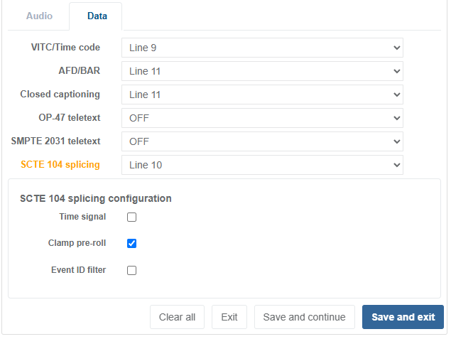
Select the Data tab.
-
From the SCTE 104 splicing drop-down list, select the line on which to insert the generated SCTE‑104 message. Valid lines ranges are:
- Line 7 to line 41 (Field 1)
- Line 569 to line 583 (Field 2)
When SCTE‑104 Splicing is enabled with a valid line number, the additional SCTE 104 splicing configuration options become available. Setting the SCTE-104 Splicing line selection to OFF hides these options.
-
Refer to SCTE 104 Splicing configuration parameters for additional settings.
-
Click Save and Continue to apply the changes.
Time Signal Conversion
Section titled “Time Signal Conversion”A time_signal() splice command may include an optional segmentation_descriptor(). When present,
this can be translated into SCTE‑104 multiple_operation_message, comprising:
time_signal_request_data(), followed byinsert_segmentation_descriptor_request_data()
Configuring Time Signal Conversion
Section titled “Configuring Time Signal Conversion”To enable or disable time signal conversion:
-
Enable Splicing by following Configuring SCTE-104 output.
-
Select the Time Signal checkbox to enable or disable conversion of the
time_signal()splice command. -
Click Save and Continue to apply the changes.
Event ID filtering
Section titled “Event ID filtering”Event ID filtering, also referred to as Addressable DPI, allows the Receiver service to filter out
undesired DPI events according to the splice_event_id in the incoming SCTE-35 messages. Typically,
this would be used at downlink sites.
For example, Receiver services can be grouped so that:
- all receivers in Group 1 output only messages with
splice_event_id= 1, - all receivers in Group 2 output only messages with
splice_event_id= 2, and so on.
When Event ID filtering is enabled, each SCTE‑35 message is evaluated against the filter. Only messages that match the filter are converted to SCTE‑104 for output; all others are dropped. When filtering is disabled, all SCTE‑35 messages are converted to SCTE‑104.
How the Filter Works
Section titled “How the Filter Works”The filter compares two values:
- A = bitwise AND of the Event ID mask and
splice_event_idfrom thesplice_insert()message - B = bitwise AND of the Event ID mask and the user-defined Event ID value
If A equals B, the SCTE‑35 message passes the filter and is converted to SCTE‑104.
Example
Worked example with:
- SCTE-35 message with the splice_event_id = 0xA0001200
- Event ID mask = 0x10001000
- Event ID value = 0x00001000
                        Binary                              (Hex)splice_event_id:        10100000 00000000 00010010 00000000 (0xA000 1200)Event ID mask:      AND 00010000 00000000 00010000 00000000 (0x1000 1000)Result A:           =   00000000 00000000 00010000 00000000 (0x0000 1000)
Binary (Hex)Event ID value: 00000000 00000000 00010000 00000000 (0x0000 1000)Event ID mask: AND 00010000 00000000 00010000 00000000 (0x1000 1000)Result B: = 00000000 00000000 00010000 00000000 (0x0000 1000)- A = 0x00001000
- B = 0x00001000
Since A equals B, the SCTE‑35 message passes the filter and is converted to SCTE‑104.
Configuring Event ID filtering
Section titled “Configuring Event ID filtering”To configure the Event ID filter:
-
Enable Splicing by following Configuring SCTE-104 output.
-
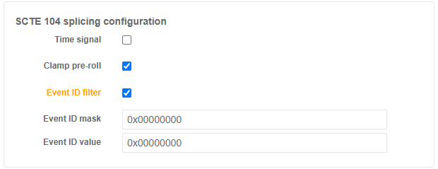
Select the Event ID filter checkbox to enable filtering.
-
Set the Event ID mask with a value in hexadecimal.
-
Set the Event ID value with a value in hexadecimal.
-
Click Save and Continue to apply the changes.