Configure the decoding
After MK.IO Beam locks to an input transport stream, it enables selection of available services (programmes) for decoding. These services are then processed and output according to the configured decoding and output parameters.
Service selection
Section titled “Service selection”Before you start, ensure at least one Receiver service has started and is in a Running state. The input should be configured and locked to a valid input.
-
From the Home page, select the RECEIVER item from the required feed then click
 to edit.
 -
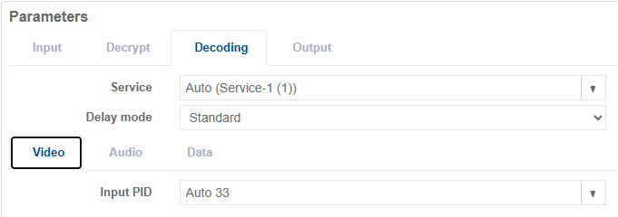
From the Parameters section, select the Decoding tab.
-
Select a service from the Service drop-down list to decode. The first video and audio components listed in the service PMT will be automatically selected for decode.
-
Click Save and Continue to apply change.
It may be necessary to configure the correct Configuration Type.
Delay Mode
Section titled “Delay Mode”By default, the Delay mode is set to Standard, which is optimised for most decode use cases. For more information, see the Delay Modes section.
Checking Service Status
Section titled “Checking Service Status”Service status can be checked on the same Edit page or by viewing the Stats
 page.
page.
-
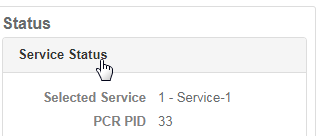
Check Service Status panel with the following fields:
- Selected Service shows the service number and service name
- PCR PID shows the current PCR PID in use
-
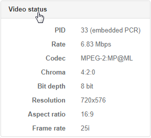
Check the Video Status panel. The video PID, component bit rate, codec being used, resolution, picture aspect ratio and frame rate are displayed.
-
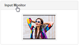
Check the Input Monitor panel. This displays a thumbnail of the decoded video which is updated every 5 seconds.
-
Check the Audio Status panel. The audio PID, status and codec are displayed. Hover over each audio status field to display additional information, including channel mode, language and bit rate.
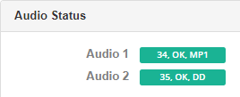
The colour of each field provides a quick indication of audio decode status, with green indicating success and red indicating errors.
Video Decoding
Section titled “Video Decoding”See the Video Decoding section in the technical Reference documentation for video codec and resolution capabilities supported by MK.IO Beam.
Configure video decoding
Section titled “Configure video decoding”The video PID is automatically selected based on the configured Service Selection. This can be overridden as follows:
-
From the Parameters section, select the Decoding tab.
-
Select the Video tab.
-
Select a video PID from the Input PID drop-down list, or manually enter a PID value.
-
Click Save and Continue to apply change.
Audio decoding
Section titled “Audio decoding”Up to 8 audio components (stereo pairs), or 16 audio channels, can be decoded per Receiver service.
See the Audio Decoding section in the technical Reference documentation for details of the audio codecs supported by MK.IO Beam for decoding and pass-through.
Decode Channel Configuration
Section titled “Decode Channel Configuration”Each audio component selected for decoding can be configured with a different number of output channels for embedding in the output stage.
| Decode Channel Configuration | Use case | Output channels |
|---|---|---|
| Stereo | Decode stereo, dual mono, mono, joint stereo or 5.1 downmix | 2 |
| 5.1 | Decode 5.1 audio | 6 |
| 16 | Mandatory for MPEG-H decode | 16 |
| Pass-through | No decode. Use this option for compressed audio output | 2 |
Configure audio decoding
Section titled “Configure audio decoding”Before you start, ensure Service Selection is configured.
-
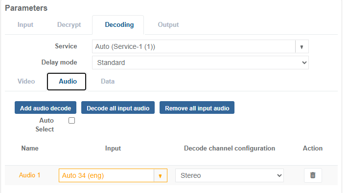
From the Parameters section, select the Decoding tab.
-
Select the Audio tab to view the audio decode table.
-
The first decoded audio Name is automatically given the reference Audio 1. This reference is used when configuring audio in the output stage.
-
Select an audio PID from the Input drop-down list, or manually enter a PID value.
-
Select the appropriate Decode channel configuration.
-
Click Save and Continue to apply change.
Add Audio Decode
Section titled “Add Audio Decode”To add a single audio entry (for example, Audio 2) to the audio decode table:
-
From the Parameters section, select the Decoding tab.
-
Select the Audio tab to view the audio decode table.
-
Select Add audio decode to create a new entry.
-
Configure the new entry by following the steps in Configure audio decoding above.
Remove Audio Decode
Section titled “Remove Audio Decode”To remove a single audio entry from the audio decode table:
-
From the Parameters section, select the Decoding tab.
-
Select the Audio tab to view the audio decode table.
-
Click the
 icon on the audio decode entry.
Decode All Input Audio
Section titled “Decode All Input Audio”To add audio entries for all detected audio components in the configured Service Selection (this option is only effective when a valid input is incoming):
-
From the Parameters section, select the Decoding tab.
-
Select the Audio tab to view the audio decode table.
-
Select Decode all input audio to create entries for all detected audio components (up to a maximum of eight, Audio 8).
-
For each entry, select the appropriate Decode channel configuration.
Remove All Input Audio
Section titled “Remove All Input Audio”To remove all audio entries from the audio decode table:
-
From the Parameters section, select the Decoding tab.
-
Select the Audio tab to view the audio decode table.
-
Select Remove all input audio to empty the audio decode table.
Auto Select
Section titled “Auto Select”When Auto Select is enabled, the receiver automatically selects and configures audio components based on the PMT order of the configured Service Selection from the input transport stream. Existing manual audio decode entries are replaced with automatically generated entries, each configured with the Decode channel configuration set to Stereo.
This feature also manages the embedding of audio channels in the output stage. It is best suited for SDI output and is not recommended for use with SMPTE ST 2110 output configurations.
After a PMT update, the currently assigned audio decoders are reviewed and may be modified:
- Automatic audio selection is based on PMT order, so audio components may be moved, added, or removed.
- Only the first 8 audio components (Stereo) are automatically selected and embedded in the output stage.
To configure Auto Select:
-
From the Parameters section, select the Decoding tab.
-
Select the Audio tab to view the audio decode table.
-
Select the Auto Select tick box.
Data decoding
Section titled “Data decoding”Up to 8 data components can be decoded per Receiver service.
See the Ancillary Data section in the technical Reference documentation for the ancillary data types supported by MK.IO Beam.
The following data types, encapsulated in video (for example, SEI messages or MPEG-2 user data) or as packetised elementary stream (PES) packets, can be processed by the Receiver service and converted for output, for example to SDI.
| Format | Output format |
|---|---|
| AFD / Bar data | SMPTE ST 2016 |
| Teletext | OP-47 / SMPTE ST 2031 |
| Closed captions | SMPTE ST 334 for EIA-708-B |
| Timecode | SMPTE ST 12 + RP 188 |
| Generic VANC | SMPTE ST 2038 |
| SCTE-35 | SCTE-104 |
Data Type Configuration
Section titled “Data Type Configuration”Where data types are carried as data components (PES packets) in the transport stream, they can be selected as described in the sections below.
Each selected data component must be configured with the appropriate Data Type configuration to enable embedding at the output stage.
| Data Type Configuration | Use case |
|---|---|
| Ancillary | Extraction of generic VANC data |
| Teletext | Extraction of CCIR Teletext System B (EBU Teletext) for conversion to OP-47 or SMTPE ST 2031 |
| SCTE 35 Splicing | Extraction of SCTE-35 data for conversion to SCTE-104 |
Configure data decoding
Section titled “Configure data decoding”Before you start, ensure Service Selection is configured.
-
From the Parameters section, select the Decoding tab.
-
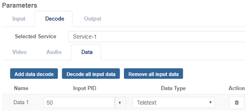
Select the Data tab to view the data decode table.
-
Select Add data decode to create a new entry. The first decoded data Name is automatically given the reference Data 1.
-
Select a data PID from the Input drop-down list, or manually enter a PID value.
-
Select the appropriate Data type configuration.
-
Click Save and Continue to apply change.
Add Data Decode
Section titled “Add Data Decode”To add a single data entry (for example, Data 2) to the data decode table:
-
From the Parameters section, select the Decoding tab.
-
Select the Data tab to view the data decode table.
-
Select Add data decode to create a new entry.
-
Configure the new entry by following the steps in Configure data decoding above.
Remove Data Decode
Section titled “Remove Data Decode”To remove a single data entry from the data decode table:
-
From the Parameters section, select the Decoding tab.
-
Select the Data tab to view the data decode table.
-
Click the
icon on the data decode entry.
Decode All Input Data
Section titled “Decode All Input Data”To add data entries for all detected data components in the configured Service Selection (this option is only effective when a valid input is incoming):
-
From the Parameters section, select the Decoding tab.
-
Select the Data tab to view the data decode table.
-
Select Decode all input data to create entries for all detected data components (up to a maximum of eight, Data 8).
-
For each entry, select the appropriate Data type configuration.
Remove All Input Data
Section titled “Remove All Input Data”To remove all data entries from the data decode table:
-
From the Parameters section, select the Decoding tab.
-
Select the Data tab to view the data decode table.
-
Select Remove all input data to empty the data decode table.