Stream Processing tab
Transport Stream properties
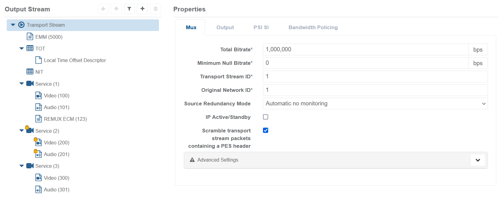
Mux Parameters

| Parameter name | Description | Possible values |
|---|---|---|
| Total Bitrate* | Dimensions the bandwidth at multiplexer output. Embeds PSI and NULL bit rates, as well as the sum of the video/ audio/private stream bit rates embedded in multiplexer output. | 0 to 200000000 bps |
| Minimum Null Bitrate* | Reserves NULL packet bandwidth. If component bitrate + null bitrate > total bitrate then component packets will be discarded | 0 to 200000000 bps |
| Transport Stream ID* | Sets the Transport Stream ID in the output PAT, SDT and NIT (if enabled) | 0 to 65535 |
| Original Network ID* | Sets the Original Network ID in the output SDT and NIT (if enabled) | 0 to 65535 |
| Source Redundancy Mode | See redundancy mode paragraph. | Dropdown menu: Automatic no monitoring, Manual no monitoring, Automatic with monitoring, Manual with monitoring. |
| IP Active/Standby | Enable Active/Standby for IP output | Tick box, disabled by default |
| Scramble transport stream packets containing a PES header | TS packets containing a PES header are scrambled if scrambling is required for the current service. | Tick box, enabled by default |
Mux Advanced Settings
These settings are only for advanced configurations. Default values should be suitable for the majority of use cases.
| Parameter name | Description | Possible values |
|---|---|---|
| Input jitter buffer latency | The latency on each input used to absorb input jitter. Requires a service restart to apply. Reducing this value can reduce the latency of the service in the multiplexing stage. However, depending on the service configuration (FEC and or RTP enabled) and on the input bitrate, reducing this value could lead to insufficient buffering available for the muxing process. In such case, an alarm will be raised to notify about possible problems in the output stream. | 10 to 30000 ms |
| Scrambling latency | The added latency during which scrambling occurs. | 10 to 30000 ms |
| ASI Active/Standby | Whether ASI outputs should stop when in standby or not. | Tick box |
| Copy SDT as SDT Other | Controls which other transport streams will receive a copy of the SDT | Dropdown menu: To all networks, To same network, Do not copy |
| Hide transport stream | Hide this transport stream in the NIT included in other transport streams of the same DVB network | Tick box |
| ASI output buffer latency | The output latency added when using ASI. Applies only to DekTec 2174b and 2178 cards when being used for ASI output. Latencies below 50ms are not recommended. | 10 to 30000 ms |
| IP output buffer latency | The IP output latency. | 10 to 30000 ms |
Output Parameters
IP

| Parameter name | Description | Possible values |
|---|---|---|
| Output Name* | Used to identify the specific output | String of max 32 characters |
| Type | Select the output type | Dropdown menu: IP, ASI, RIST |
| Network interface | Name of network interface used for the output transport stream (as seen by the operating system). | String of max 32 characters |
| Stream Address* | Unicast or multicast destination IPv4 address for the Transport Stream packets | IPv4 address |
| Destination UDP port* | Destination port for the Transport Stream packets | 0 to 65535 |
| User-specified source details | If unticked, the output transport stream source IP address will be the IP address of the specified Network interface. Otherwise, the source IP address field and source UDP port field of the output IP packet headers will be populated with the user-specified source IP address and source UDP port regardless of the IP address of the specified Network interface. The specified Network interface will not respond to ARP or PING on a user-specified source IP address (unless the user-specified source IP address is the same as the specified Network interface). | If ticked, Source IP address and Source IP port field will be required (respectively, IPV4 address and value between 0 and 65535) |
| Time to live | Sets the IPv4 Time To Live field (maximum number of routersa multicast packet can reach before being discarded) | 0 to 255 |
| IP encapsulation | Type of IP encapsulation. E.g., FEC packets can be generated to protect the media packets. | Dropdown menu: UDP, RTP, FEC |
| Server filter | Assigned servers matching this pattern will output using these settings. * = wildcard of any length. For example: s*1 would match 'server 1' and not 'server 2' | String of max 32 characters |
| Output in the clear | Output all components in the clear. Overrides SCG config. | Tick box, disabled by default |
ASI
If ASI mode is selected, the available configuration parameters will be as follows.

| Parameter name | Description | Possible values |
|---|---|---|
| Output Name* | Used to identify the specific output | String of max 32 characters |
| Type* | Select the output type | Dropdown menu: IP, ASI, RIST |
| Connector(s)* | [ASI only] Specify one or more ASI card connectors to output this Transport Stream on. ASI connector configuration is covered in ASI Card Configuration Tool | Comma-separated list of integers greater than zero |
| 204 Byte Packet Length | [ASI Only] Changes ASI output from 188 to 204 byte packets. Requires a service restart to apply. | Tick box, disabled by default |
| Server filter | Assigned servers matching this pattern will output using these settings. * = wildcard of any length. For example: s*1 would match 'server 1' and not 'server 2' | String of max 32 characters |
| Output in the clear | Output all components in the clear. Overrides SCG config. | Tick box, disabled by default |
RIST
If RIST mode is selected, the available configuration parameters will be as follows.

| Parameter name | Description | Possible values |
|---|---|---|
| Output Name* | Used to identify the specific output | String of max 32 characters |
| Type* | Select the output type | Dropdown menu: IP, ASI, RIST |
| Mode* | Configures the RIST output to operate in either Listener or Caller mode. | Dropdown menu: Listener, Caller |
| Network interface | In RIST Listener mode, the interface to listen on. Not available for Caller mode. | String of max 32 characters |
| Listener Address* | In RIST Caller mode, configures the address of the remote RIST Listener to connect to. | IPv4 address |
| Listener Port* | Configures the port to either listen on or call, in Listener and Caller mode respectively. | 0 to 65535 |
| Maximum Caller Connections | If Listener mode is selected, configures the maximum allowed connections to the RIST output. | 1 to 65535 |
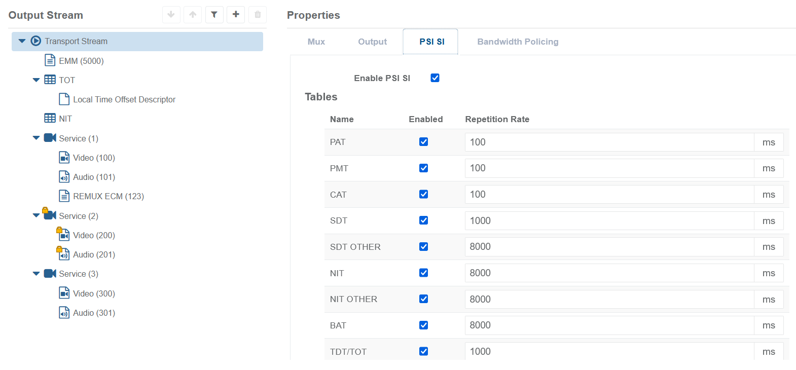
PSI SI Parameters

If the Enable or disable PSI SI tick box is enabled (default), it is possible to override the repetition rate (in ms) for any of the listed tables.
Bandwidth Policing Parameters

Use the Add Group button to add as many groups as needed.
Use the button on the right to remove a group.
For each added group, the following parameters will be required:
| Parameter name | Description | Possible values |
|---|---|---|
| Name* | Used to identify the specific bandwidth policing group | String of max 32 characters |
| Bitrate | Maximum bitrate allowed for the group. If the total bitrate of the components in the group exceeds this value, packets will be dropped and alarms raised. | 0 to Total Bitrate (as set in the Mux parameters) |
TOT and NIT Properties
TOT
TOT: no configuration parameters available.

NIT

| Parameter name | Description | Possible values |
|---|---|---|
| Network ID* | Sets the Network ID used in the output NIT (if enabled) | 0 to 65535 |
Service Properties
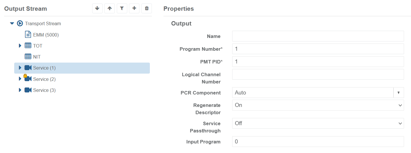
Output parameters

| Parameter name | Description | Possible values |
|---|---|---|
| Name | A user-friendly name for the service. Note that this is not the Service Name, which must be configured via the Service Descriptor. | String of max XX characters |
| Program Number* | Program Number used to populate the output PMT and ServiceID in the SDT | 1 to 65535 |
| PMT PID* | Output PMT PID | 0 to 8190 |
| Logical Channel Number | Sets the Logical Channel Number in the NIT (if NIT is enabled and the Logical Channel Descriptor is present). Values above 1023 are only allowed if the descriptor specifies the NorDig range.Leave blank if not required. | 1 to 16383 |
| PCR Component | Dropdown menu: Auto, Manually specified PID, None | |
| Regenerate Descriptor | Dropdown menu: On, Off | |
| Service Passthrough | Automatically add components and descriptors from the specified input service to this output service. If the specified input service cannot be found, there will not be an output PMT or PAT reference. This behaviour is dynamic and the output PAT/PMT references will track changes to the incoming service. | Dropdown menu: Off, On |
| Input Program | Specifies the input Program Number to search for the incoming PMT in order to find the required input Service | 0 to 65535 |
If Service Passthrough is set to On, additional configuration parameters will be available:

| Parameter name | Description | Possible values |
|---|---|---|
| Dropped PIDs | Comma separated list of PIDs which will not be passed through to the output service | |
| Monitor health of all signalled input components | Health of all signalled components in source PSI/SI will be monitored. If Source redundancy mode is not manual, health failure of any of these components will result in a source switch if a healthy alternative is available | Tick box, disabled by default |
| Bandwidth Policing Group | If any Bandwidth Policing Group has been defined for the transport stream (see previous paragraph), the list of all group names will appear as a dropdown menu. Assign the service to one of the groups or leave the selection empty to avoid policing it. | Dropdown menu: names of any defined bandwidth policing group. |
Sources parameters
Define the parameters for the first input and then use the “+Add” Tab to define more other inputs.
For each input, new parameters can be configured manually or, if a source already exist, it can be shared between different services and components. This will be highlighted with red text as in the picture below.
It is recommended to add a User-defined name to the source to make it easily recognizable. The name will also be used to rename the tab.

| Parameter name | Description | Possible values |
|---|---|---|
| User defined name for source* | Name and also source tab name. This is the identifier of the current input which will also be used, when saving the configuration, to rename the current Source Tab. | String of max 32 characters |
| Type | Type of input: IP, ASI or RIST | Dropdown menu: IP, ASI, RIST |
| Lock without seeking input PCR | Lock without seeking input PCR | Tick box, disabled by default |
| Output Drop On Input TS Loss | If this input transport stream is lost, all the Transport Stream outputs will be stopped. | Tick box, disabled by default |
IF TYPE = IP (as in the previous figure)
| Parameter name | Description | Possible values |
|---|---|---|
| Network Interface | Input network interface name specifies the one (as seen by the operating system) used to capture Transport Stream packets. | String of max 32 characters |
| Destination IP Address* | Destination IP address used to capture Transport Stream packets | IPv4 address |
| Port* | Destination UDP used to capture Transport Stream packets | 0 to 65535 |
| FEC Enabled | If selected, the IP encapsulation for the input TS is expected to be FEC. When enabled the FEC packets can be used to try to recover missing media packets. Requires RTP. | Tick box, disabled by default |
| Source Address | List of comma separated IPv4 addresses used to filter the sources of the current input (based on IGMPv3 protocol). Examples: 172.18.2.39 or 172.18.2.39,172.18.2.40 |
IF TYPE = ASI
| Parameter name | Description | Possible values |
|---|---|---|
| Connector* | An ASI connector index, greater than zero. In case of multiple ASI cards available on the same box, this is the logical identifier of the connector (see ASI configuration tool paragraph) | 1 to 65535 |
IF TYPE = RIST
| Parameter name | Description | Possible values |
|---|---|---|
| Mode* | Configures the RIST output to operate in either Listener or Caller mode. | Dropdown menu: Listener, Caller |
| Network interface | In RIST Listener mode, the interface to listen on. Not available for Caller mode. | String of max 32 characters |
| Listener Address* | In RIST Caller mode, configures the address of the remote RIST Listener to connect to. | IPv4 address |
| Listener Port* | Configures the port to either listen on or call, in Listener and Caller mode respectively. | 0 to 65535 |
Configuration of RIST inputs is only available via the Properties panel.